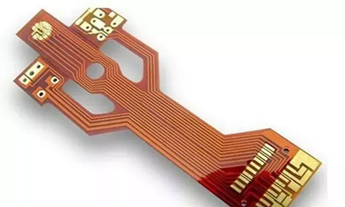
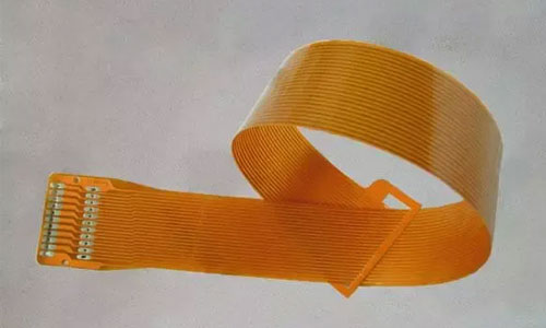
A Flexible Printed Circuit (FPC), also known as a flex circuit or flex PCB, is a highly reliable and flexible printed circuit board made with a polyimide or polyester film substrate. FPCs are lightweight, thin, and can be easily bent and folded, making them highly desirable for various applications.

FPCs were initially developed in the 1970s in the United States for the advancement of aerospace and rocket technologies. They enable the integration of a large number of precise components in narrow and limited spaces by embedding circuit designs into flexible, thin plastic films. These circuits can be bent, folded, and are lightweight, compact, have good heat dissipation, and are easy to install, breaking through the limitations of traditional interconnect technologies. The materials used in the structure of a flexible circuit include insulation films, conductors, and adhesives.
Materials Used in FPCs:
Insulation films:
Insulation films form the foundation layer of the circuit. Adhesives bond the copper foil to the insulation layer. In multilayer designs, they are bonded together with inner layers. They also serve as protective covers to isolate the circuit from dust and moisture, reduce stress during flexing, and the copper foil forms the conductive layer.
Conductors:
Copper foil is commonly used in flexible circuits. It can be electroplated (ED) or rolled. ED copper foil has a shiny side and a processed dull side. It is a flexible material that can be produced in various thicknesses and widths. The dull side of ED copper foil is often specially treated to improve its adhesive properties. Rolled copper foil has both flexibility and a smooth, hard surface, making it suitable for applications that require dynamic flexing.
Adhesives:
Adhesives are used to bond the insulation film to the conductive material and can also serve as a cover or protective coating. The difference between a covering adhesive and a coating adhesive lies in the application method. A covering adhesive is used to cover the insulation film and form a multilayer circuit structure. Covering adhesive application is done through screen printing.
Not all multilayer structures contain adhesives. Adhesive-free multilayer structures result in thinner circuits with greater flexibility. Compared to adhesive-based multilayer structures, adhesive-free circuits have better thermal conductivity due to their thin structure and the elimination of thermal resistance caused by adhesives. This allows them to be used in work environments where circuits based on adhesive-based multilayer structures are not suitable.
Basic Structure:
Copper foil substrate: Copper Film.
Copper Foil: Electrodeposited copper and rolled copper are two common types, available in thicknesses of 1oz, 1/2oz, and 1/3oz.
Substrate Film: Available in thicknesses of 1 mil and 1/2 mil.
Adhesive: Bonding agent, thickness determined by customer requirements.
Cover Film: Surface insulation use, available in thicknesses of 1 mil and 1/2 mil.
Release Paper: Prevents adhesive from adhering to foreign objects before pressing, facilitating operation.
Stiffener Film: PI Stiffener Film, used to enhance the mechanical strength of the FPC, facilitating surface mounting operations, available in thicknesses ranging from 3mil to 9mil.
EMI Shielding Film: Protects the circuit from external interference in areas with strong electromagnetic fields or high susceptibility to interference.
How to Solder:
Operation Steps:
(1) Before soldering, apply flux to the solder pads and treat them with a soldering iron to ensure good solderability, as poor solderability or oxidation of the pads can result in poor soldering. Generally, no treatment is required for the chips.
(2) Carefully place the PQFP chip onto the PCB board with tweezers, being careful not to damage the pins. Align it with the solder pads, ensuring correct placement. Set the soldering iron temperature to around 300 degrees Celsius, dip the soldering iron tip in a small amount of solder, and use a tool to press down on the aligned chip. Apply a small amount of solder to the pins at the two diagonal positions while still pressing down on the chip, soldering the pins at the two diagonal positions to secure the chip in place. After soldering the diagonal pins, recheck the chip's position for alignment. If necessary, adjust or remove and re-align the chip on the PCB board.

(3) When soldering all the pins, apply flux to the soldering iron tip and coat all the pins with flux to keep them wet. Make contact between the soldering iron tip and the end of each pin, soldering until the solder flows into the pin. During soldering, keep the soldering iron tip parallel to the pins being soldered to prevent excessive solder and bridging.
(4) After soldering all the pins, wet all the pins with solder flux for solder cleaning. Remove excess solder where needed to eliminate any short circuits or bridging. Finally, use tweezers to check for any cold solder joints. After the inspection, remove the solder flux from the circuit board. Dip a stiff brush in alcohol and carefully wipe it along the pins until the solder flux disappears.
(5) Soldering surface mount capacitors and resistors is relatively easier. Apply solder to one solder pad first and place one end of the component on it. Use tweezers to hold the component, solder one end, and then check if it is properly aligned. If it is aligned correctly, solder the other end.
Precautions:
In terms of layout, when the PCB size is too large, although soldering is easier to control, the printed lines become longer, impedance increases, noise resistance decreases, and costs increase. When the PCB size is too small, heat dissipation decreases, soldering becomes difficult to control, and problems such as mutual interference between adjacent lines or electromagnetic interference may occur.
Therefore, PCB board design must be optimized:
Shorten the interconnections between high-frequency components to reduce EMI interference.
For heavy components (over 20g), they should be secured with brackets before soldering.
Consider heat dissipation for heat-generating components to prevent large temperature differentials that may cause defects and rework. Heat-sensitive components should be kept away from heat sources.
Arrange components parallel to each other for aesthetics and ease of soldering, facilitating large-scale production. The PCB design should be a rectangular shape with a 4:3 aspect ratio.
Avoid sudden changes in wire width to prevent discontinuity in wiring.
When the circuit board is subjected to heat for a long time, the copper foil is prone to expansion and
Contact: Pamela
Phone: +86 189 6365 3253
E-mail: info@industryprocess.com
Whatsapp:+86 189 6365 3253
Add: Yajing Industrial Park, No. 59 Shuangjing Street, Weiting Town, Suzhou Industrial Park
We chat
