The increase in the driving range of electric vehicles is achieved by improving the battery capacity and reducing the load weight of non-power components. Considering these two aspects, flexible circuit boards with small footprint and lightweight are the top choice in the electrical systems of new energy vehicles. They are widely used due to their good high-temperature reliability, simple circuit design, and compatibility. This article provides conceptual information about the performance, applications, and manufacturing of flexible circuit boards, as well as new technologies for flexible circuit board production - round-blade die cutting solutions.
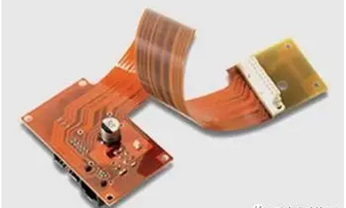
What are Flexible Circuit Boards?
Flexible circuit boards, also known as "flex boards" or "flex PCBs," are printed circuits made of flexible insulating materials. They have many advantages that rigid printed circuit boards don't have. For example, they can bend, wrap, and fold freely, allowing for flexible component assembly and wire connection in three-dimensional space. FPC can greatly reduce the size of electronic products and meet the needs of electronic products for high density, miniaturization, and high reliability. Therefore, FPC is widely used in aerospace, military, mobile communication, laptops, computer peripherals, PDAs, digital cameras, and other fields or products.
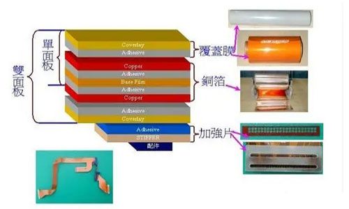
Basic Structure of Flexible Circuit Boards
Copper Foil Substrate:
Copper foil is divided into electrolytic copper and rolled copper. Common thicknesses are 1oz, 1/2oz, and 1/3oz.
Substrate Film:
Common thicknesses are 1mil and 1/2mil.
Adhesive:
Thickness is determined according to customer requirements.
Cover Film Protective Film:
Used for surface insulation. Common thicknesses are 1mil and 1/2mil.
Adhesive:
Thickness is determined according to customer requirements.
Release Liner:
To prevent adhesives from adhering to foreign substances before lamination and facilitate operations.
PI Stiffener Film:
To enhance the mechanical strength of FPC and facilitate surface mounting operations. Common thicknesses are 3mil to 9mil.
Adhesive:
Thickness is determined according to customer requirements.
Release Liner:
To prevent adhesives from adhering to foreign substances before lamination.
EMI Shielding Film:
To protect the internal circuit of the board from interference in strong electromagnetic or easily interfer.
Types and Performance of Flexible Circuit Boards
FPC (Flexible Printed Circuit) also has good heat dissipation and solderability, as well as easy installation and relatively low overall cost. The design of flexible and rigid combination also partially compensates for the slight deficiency of flexible substrates in component carrying capacity.
Flexible printed circuit boards can be divided into single-sided, double-sided, and multilayer boards. The main material used is polyimide coated copper-clad laminate. This material has high heat resistance and good dimensional stability. The final product is obtained by pressing the material together with a covering film that provides mechanical protection and good electrical insulation. The surface and inner layer conductors of double-sided and multilayer printed circuit boards are electrically connected by metallization. Currently, there are four popular types of flexible circuit boards: single-sided, double-sided, multilayer, and rigid-flex combination.
Insulation materials used for flexible assembly can be polyimide (Kapton), polyethylene terephthalate (PET), aramid fiber paper (Nomex), and polyvinyl chloride (PVC). The flexible circuit board industry is currently experiencing rapid development despite its small scale. The polymer thick film (PTF) process is an efficient and low-cost method for producing circuit boards. This process selectively prints conductive polymer ink on inexpensive flexible materials. PET is a representative flexible material used in the PTF process. PTF conductors include screen-printed metal or carbon powder fillers. PTF itself is clean and uses lead-free SMT adhesive, eliminating the need for etching.
The functions of flexible circuit boards can be divided into four types: lead line, printed circuit, connector, and integration of functions.
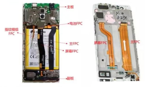
Internal structure of Huawei mobile phone (left: Honor 6, right :P9)
1) Single-sided boards
Single-sided flexible boards consist of a copper layer applied to a flexible substrate, which is then covered with a protective film, forming a flexible circuit board with only one conductive layer. Single-sided flexible boards have the lowest cost. When high electrical performance is not required and single-sided wiring is sufficient, single-sided flexible boards are preferred. This common form of flexible board is widely used in commercial applications such as inkjet cartridges and computer memory. Single-sided flexible boards have a conductive pattern chemically etched on the flexible substrate, with a rolled copper foil serving as the conductive pattern layer on the flexible insulation material surface.
2) Standard double-sided boards
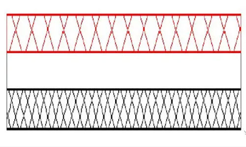
Standard double-sided flexible boards consist of two conductive layers applied to both sides of a flexible substrate, with protective films added on both sides. They have two conductive patterns formed by etching on each side of the base material. The conductive patterns on the insulation material's two sides are connected by plated holes to form a conductive path, meeting the requirements of flexible design and functionality. The cover film protects the single- or double-sided conductors and indicates the component placement.
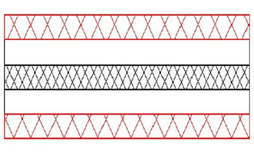
3) Substrate-based single-sided boards
Substrate-based single-sided boards consist of a pure copper foil on both sides of the circuit board, with a protective film applied to each side. They have a single conductive layer, but both sides of the board have exposed conductors.
4) Substrate-based double-sided boards
Substrate-based double-sided boards are made by bonding two layers of single-sided flexible boards made of copper-clad laminate, with adhesive bonding in specific locations. This structure has two layers separated in localized areas, providing a double-sided conductive path with high flexibility in the layered regions.
Multilayer flexible boards are made by laminating three or more layers of single-sided or double-sided flexible circuit boards together. Conductive paths are formed between different layers through drilling and electroplating, eliminating the need for complex soldering processes. Although the number of conductive layers in this flexible type can be unlimited, the assembly dimensions, the number of layers, and flexibility should be considered in the design layout to ensure ease of assembly.
5) There is also a hybrid structure flexible circuit board with multiple layers, but the conductive layers are made of different metals. This hybrid structure is mostly used in low-temperature conditions where signal conversion, heat transfer, and stringent electrical performance requirements are present. In such cases, flexible hybrid circuits are the only feasible solution.
The above classification is commonly used in the industry, and the standard "IPC-6013 Chinese Edition Flexible Printed Board Quality and Performance Specification" also provides a classification based on the number of layers, as well as the presence of reinforcement layers and holes.
According to the standard's classification, flexible printed circuit boards can be divided into the following types:
Type 1: Single-sided flexible printed boards with one conductive layer, with or without reinforcement layers.
Type 2: Double-sided flexible printed boards with two conductive layers and plated-through holes, with or without reinforcement layers.
Type 3: Multilayer flexible printed boards with three or more conductive layers and plated-through holes, with or without reinforcement layers.
Type 4: Rigid-flex combination multilayer printed boards with three or more conductive layers and plated-through holes.
Type 5: Flexible or rigid-flex combination multilayer printed boards with two or more conductive layers, without plated-through holes.
Typical Production Process of FPC
1) Single-sided board process: Engineering files - Copper foil - Preprocessing - Dry film lamination - Exposure - Development - Etching - Stripping - AOI (Automated Optical Inspection) - Preprocessing - Overlay (or ink printing) - Pre-electroplating treatment - Electroplating - Post-electroplating treatment - Pressing reinforcement - Outline punching - Electrical testing - Appearance inspection - Shipping
2) Double-sided board process: Engineering files - Copper foil - Drilling - PTH (Plated Through Hole) - Copper plating - Preprocessing - Dry film lamination - Exposure - Development - Etching - Stripping - AOI - Preprocessing - Overlay (or ink printing) - Pre-electroplating treatment - Electroplating - Post-electroplating treatment - Pressing reinforcement - Outline punching - Electrical testing - Appearance inspection - Shipping. In terms of this process, the finest line width and spacing are around 50 micrometers.
The biggest drawback is still the high cost.
If the circuit design is relatively simple, the overall size is not large, and the space is appropriate, traditional interconnection methods are generally more cost-effective. If the circuit is complex, involves multiple signals, or has special electrical or mechanical performance requirements, flexible circuit boards are a better design choice. One potential cost-saving advantage of flexible materials over rigid materials is the elimination of connectors.
The high cost of raw materials is the main reason for the high price of flexible circuit boards. Despite the expensive materials and complicated manufacturing process, the ability to fold, bend, and stack multiple layers reduces the overall component size and the amount of material used, thereby lowering the total assembly cost.
The cost of flexible circuit boards is further decreasing. Despite the aforementioned cost factors, the price of flexible assembly is decreasing and becoming comparable to traditional PCBs. This is primarily due to the introduction of updated materials, improved production processes, and structural changes. For example, in complex rigid-flex board assemblies with many layers, the use of acrylic adhesive has been eliminated.
With thinner copper layers made possible by newer materials, finer lines can be produced. Thinner copper layers make the components lighter, and the resulting lighter and thinner assemblies make flexible components more suitable for fitting into smaller spaces. In the past, we used a roller press process to adhere the copper foil to the adhesive-coated substrate. Today, it is possible to generate copper foil directly on the substrate without the need for adhesives. These technologies allow for copper layers in the sub-micron range, enabling the production of fine lines as narrow as 3 mil or even narrower in industrial applications. Removing adhesives from flexible circuit boards also makes them flame retardant.
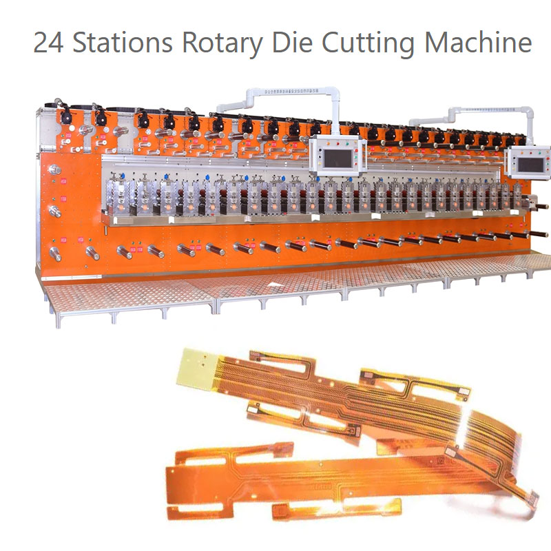
Introducing New Technologies and Advantages in Flexible Printed Circuit (FPC) Manufacturing - Rotary Die Cutting Solution
Flexible Printed Circuit (FPC) technology has revolutionized the electronics industry, offering numerous advantages over traditional rigid circuit boards. In FPC manufacturing, one innovative solution that has gained traction is the rotary die cutting method. This cutting-edge technology offers several benefits, enhancing the production and performance of FPCs.
The rotary die cutting solution utilizes specialized machinery to precisely cut FPCs into desired shapes. This technique offers high accuracy, ensuring clean and precise cuts without damaging delicate components. By incorporating computerized control systems, manufacturers can achieve consistent and repeatable results, meeting stringent quality standards.
One of the significant advantages of rotary die cutting is its ability to accommodate complex designs and intricate patterns. FPCs are often required to fit into tight spaces or unique configurations, and this technology facilitates the production of highly customized shapes and sizes. This flexibility opens up new possibilities for product designers, enabling the development of compact electronic devices with optimized functionality.
Furthermore, the rotary die cutting solution offers enhanced efficiency in FPC manufacturing. The automated nature of the process allows for faster production cycles, reducing manufacturing lead times. This efficiency translates into significant cost savings for manufacturers, enabling them to meet market demands more effectively and remain competitive in the industry.
In addition to efficiency, the rotary die cutting solution ensures the integrity and durability of FPCs. The precise cutting process prevents burrs and frayed edges, ensuring smooth operation and reducing the risk of electrical shorts or connectivity issues. This technology also minimizes stress on the FPC material, preserving its structural integrity and ensuring long-lasting performance.
The rotary die cutting solution has revolutionized FPC manufacturing, providing an effective and reliable method for producing high-quality flexible circuit boards. Its ability to accommodate complex designs, improve efficiency, and ensure durability make it an indispensable technology in the electronics industry.
In conclusion, the rotary die cutting solution is an innovative technology that enhances the production and performance of flexible printed circuits. Its precision, flexibility, efficiency, and durability advantages contribute to the advancement of FPC manufacturing. As the demand for FPCs continues to grow, this cutting-edge solution plays a crucial role in meeting the evolving needs of the electronics industry, enabling the development of more compact and capable electronic devices.
Contact: Pamela
Phone: +86 189 6365 3253
E-mail: info@industryprocess.com
Whatsapp:+86 189 6365 3253
Add: Yajing Industrial Park, No. 59 Shuangjing Street, Weiting Town, Suzhou Industrial Park
We chat
